[Home]
Table of contents
Code for this is in CameraMatcher5.java.
Suppose that we have a still photo (or a video where the camera
set up does not change). We want to insert some computer
generated objects in the scene.
Thus the composite scene has constributions from two camera, the
original one and the CG one. For the insertion to occur
seamlessly the two camera must have matching settings. While we
have complete control over the CG camera, the specifications of
the real camera are more difficult (if not impossible) to
obtain. Here we shall discuss how to achieve the camera matching
even when the real life camera parameters are completly
unknown. For this we need to use a calibration shot. Also we
shall use Art of Illusion for the CG part.
The two worlds (real and CG) are to be matched. For this we need
some common reference object whose position w.r.t. both the
This will be a square frame that we hold in the calibration shot.
We shall consider the frame to be the unit square in
the $xy$-plane in the CG world.
Using some mathematics (given below) we shall work out the
position and orientation of the real camera w.r.t the CG coordinate system.
Then we shall build our CG object and place a CG camera at that
position with that orientation. The rendered image will be ready
to be inserted in the scene (with just 2D dilation and
translation).
We want to find the position and orientation of the real
camera. That means 6 numbers (3 for position and 3 for
orientation, say as Euler angles). We have 4 points (the 4
vertices of the square) for which we know the CG coordinates and
the pixel coordinates. So we get 8 equations (each pixel means 2
coordinates). These involve the 6 unknown quantities plus the
unknown image resolution. All the 7 unknown quantities are
hopelessly confounded in the 8 equations. When you add the
additional fact that the Euler angles are not unique (i.e., there
are multiple solutions), the task looks truly daunting.
However, we simplify the task using a crucial observation:
The 4
points are chosen in such a way that we can find the vanishing
points (VPs) in the $x$- and $y$-directions of the CG
world. These VPs involve only the orientation and the pixel
resolution. So basically this eliminates 3 parameters.
Our input consists
of $(o_1,o_2),$ $(p_1,p_2),$ $(q_1,q_2)$
and $(r_1,r_2).$ We compute the VPs $(x_1,x_2)$
and $(z_1,z_2).$ All pixel coordinates are shown in
blue. All CG coordinates are shown in red.
Next we shall link the position of the VPs with the camera
orientation.
A camera has 7 parameters (3 for position, 3 for orientation, and
1 for pixel resolution). We need to find all these. Here we shall
employ a trick: we shall work w.r.t. a coordinate system attached
to the camera. Since this is going to be a source of confusion,
let us write down the three coordinate systems we are using:
-
Pixel coordinate system: This is a 2D system to
identify points on the image. Origin is at the centre of the
image (assumed to be the point straight in front of the camera,
i.e., the image has not been cropped). $y$-axis is
vertically upwards, $x$-axis is towards the right.
-
CG coordinate system: The coordinate system shown in
red above. This is the 3D coordinate system used when building
the CG object.
-
Camera coordinate system: This is the 3D coordinate
system attached to the camera. See the diagram below.
The camera lens is at the origin of this
coordinate.
The up direction is along
the $y$-axis. The $x$-axis is towards the
right. The $z$-axis is looking behind the camera. The screen
is considered to the plane $z=-\sigma$ for
some $\sigma>0.$ Any point $(x,y,z)$
is projected to $(p,q,-\sigma)$ on this plane. The camera reports
this as $(p, q)$ in pixel coordinates. The
pixel coordinates system has origin at the centre of the image (which
is assumed not be cropped). Clearly
$$
p = -\frac{\sigma x}{z}, q = -\frac{\sigma y}{z}.
$$
Now take any 3D line not parallel to the screen. Its slope can be
expressed as $(m,n,-1),$ since the $z$-component must
be nonzero. Pick any point $(a,b,c)$ on the line. Then the
parametric form of the line is
$$
(a,b,c)+t(m,n,-1) = (a+tm,b+tn,c-t),
$$
for $t\in{\mathbb R}.$ This projects to pixel
$$
\sigma \left( -\frac{a+tm}{c-t}, -\frac{b+tn}{c-t}\right).
$$
As $t\rightarrow\infty,$ this approaches
$\sigma (m, n).$
Thus the VP depends only on the slope. This is as
expected. Parallel lines having the same slope "meet" at the same VP.
Now specialise to our case. We are working with two VPs, along
the $x$-axis and the $z$-axis. Let the slopes of these
be
$(m_x,n_x,-1)$ and $(m_z,n_z,-1).$ Since these are
mutually perpendicular, their dot product vanishes:
$$
m_x m_z + n_x n_z + 1 = 0.
$$
We have found out
$$
(x_1,x_2) = \sigma (m_x,n_x) \mbox{ and } (z_1,z_2) = \sigma (m_z,n_z).
$$
Clearly,
$$
(x_1,x_2)\bullet (z_1,z_2) = -\sigma^2.
$$
Since $\sigma>0,$ we have found out one parameter of the
camera.
Now that $\sigma $ is known, we also know $m_x,n_x,
m_z$ and $n_z,$ i.e., the orientation of the axes.
Indeed, we can write down the rotation matrix $R = [\vec u_1
~~\vec u_2 ~~ \vec u_3],$ where $\vec u_1$ and $\vec
u_2$ are unit vectors along the $x$- and $z$-axes,
respectively, of the CG coordinates system, while $\vec u_2 = \vec u_3\times \vec u_1.$
This requires a bit of careful handling, as there are two unit
vectors along any straight line. Basically, one has to understand
from the photo if the axes are coming towards the camera or away
from it, and decide upon the sign accordingly.
So we have obtained the complete orientation of the CG world
w.r.t. the camera coordinates system.
All that remains to be done is to locate the origin of the CG
world w.r.t. the camera coordinates system.
Clearly, it must be of the form $\left(\frac{o_1}{\sigma},
\frac{o_2}{\sigma},-1\right)t$ for some $t\in{\mathbb R}.$
We shall find that $t.$
The point at the tip of the $x$-axis of the CG world
is $\left(\frac{o_1}{\sigma}, \frac{o_2}{\sigma},-1\right)t +\vec u_1$.
This point projects to image pixel $(p_1,p_2).$
So
$$
\frac{o'_1t+u_{11}}{t-u_{13}} = p'_1,
$$
where $o'_1 = \frac{o_1}{\sigma}$ and $p'_1 = \frac{p_1}{\sigma}.$
Solving
$$
t = \frac{p'_1 u_{13} +u_{11}}{p'_1 - o'_1} = \frac{p_1 u_{13}+u_{11} \sigma }{p_1 - o_1}.
$$
So we get a value of $t.$ Notice that there are two
equations here (both leading to the same value
of $t$). Similarly, we can also work out the (same) value by
considering $(q_1,q_2)$ or $(r_1,r_2).$
Let us summarise our final products so far:
- location of the CG origin $\vec o$ w.r.t. the camera
coordinates.
- The CG axes unit vectors $\vec u_1, \vec u_2,\vec u_3$
w.r.t. the camera coordinates.
So far we have expressed the CG coordinates in terms of the
camera coordinates. Our original aim was just the opposite, viz,
expressing the camera position and orientation in terms of the CG
coordinates system.
The location of the camera is just $-R'\vec o$.
The orientation matrix is $R ^{-1} = R'$ .
There are two ways
to specify orientation of an object in AoI: either via Object Layout panel or via
Object Transform dialogue. These behave differently. Use the
Object Layout panel to set initial values (typically 0,180,0 for
the camera). All subtle changes must be done via the
Object Transform dialogue, as the transform propagates to the
children. Here first the $z$-rotation is done (positive is
counterclockwise). Then $y$-rotation around
the global $y$-axis, and then around the
global $x$-axis.
This may be demonstrated using the following R script:
R1 = function(theta1) {
    theta1 = theta1*pi/180
    c1 = cos(theta1)
    s1 = sin(theta1)
    rbind( c(1,0,0), c(0,c1,-s1), c(0,s1,c1))
}

R2 = function(theta2) {
    theta2 = theta2*pi/180
    c2 = cos(theta2)
    s2 = sin(theta2)
    rbind( c(c2,0,s2), c(0,1,0), c(-s2,0,c2))
}

R3 = function(theta3) {
    theta3 = theta3*pi/180
    c3 = cos(theta3)
    s3 = sin(theta3)
    rbind( c(c3,-s3,0), c(s3,c3,0) , c(0,0,1))
}

R = R1(30) %*% R2(40) %*% R3(50)
> R
       [,1]   [,2]   [,3]
[1,] 0.4924 -0.587  0.643
[2,] 0.8700  0.310 -0.383
[3,] 0.0252  0.748  0.663
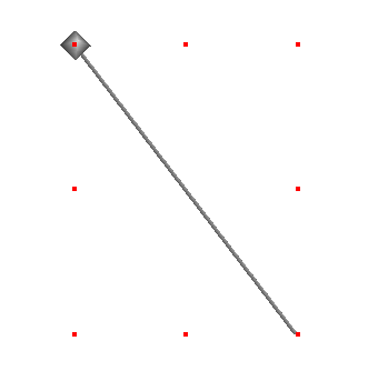
In AoI we create a line (a thin cylinder, actually)
along $y$-axis from $-1$ to 1. Also create a dot (a
small sphere) at $(-0.587,0.310,0.748)$, which is the second
column of $R.$ Apply the rotation
and you'll see a tip of the line just touch the dot:
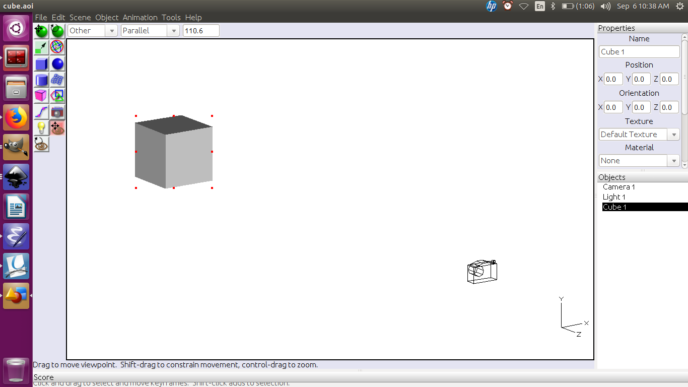
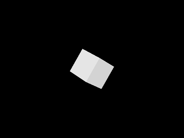
Next, take an axis-aligned unit cube with centre at the origin.
The camera looks at it along negative $z$-direction
from $(0,0,10).$
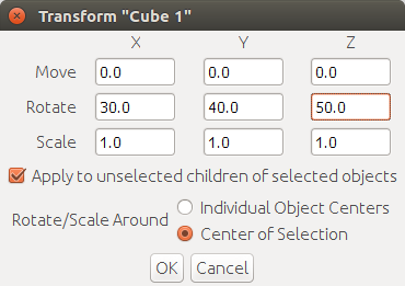
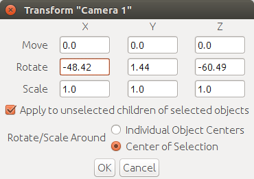
Rotate the cube by
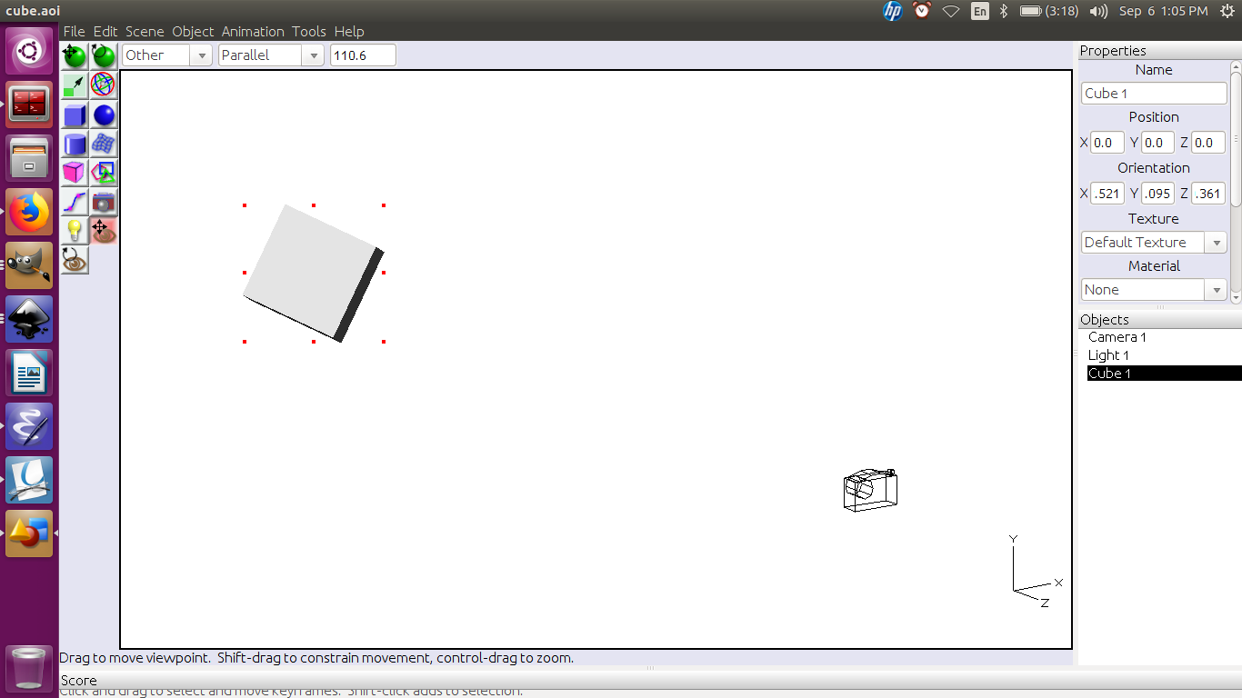
This produces
Render to get
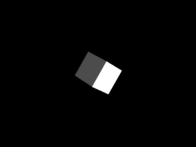
Now reset the cube to its original orientation. Set the camera
position to $R'(0,0,10)' = (0.252,7.478,6.634)'$. Also
transform its orientation by
Render to get
Create the CG object using the unit square as the reference. It
is a good idea to locate the model on or very close to the unit
square. Then place the camera at the location $-R'\vec o$
using the position panel. Also set the orientation to
0,180,0. This corresponds to looking in the
negative $z$-direction. Next, use the transform panel to set
the rotate angles to the Euler angles for $R'.$
That's it!